usb cable wiring diagram
This cable is most commonly used in mobile charger for charging mobile phones and as a USB data cable to connect mobile devices to tranfer files and images between personal computers and phones. A circuit is usually composed by many components.

Otg Usb Cable Wiring Diagram Usb Power Wiring Diagram Obd2 To Usb Cable Wiring Diagram Usb 2 0 Cable Diagram Powered Usb Hub Wiring D Otg Old Computers Usb
This USB pin-out diagram shows the USB cable often connected to phones to charge them or transfer data.

. Two for power 5v GND and two for differential data signals labelled as D and D- in pinout. USB Data usually GREEN wire should be 28 AWG. Not only will it assist you to achieve your required final results faster but in addition make the complete process less difficult for everyone.
Usb Wiring Diagram Homemade Obd2 To Usb Cable Print the cabling diagram off plus use highlighters in order to trace the circuit. Usb cable wiring diagram You will want a comprehensive expert and easy to understand Wiring Diagram. In order to utilize a USB Wiring Diagram you need to initially understand what kinds of cable televisions are readily available.
A computers serial com port dte is usually a male port as shown below and any peripheral devices you connect to this port usually has a female connector dce. Below is the figure showing the pinout diagram of the USB micro-B and USB-A wiring diagram. Components of Usb To Rca Cable Wiring Diagram and A Few Tips.
For audio output it will include a. The first component is symbol that indicate electrical element from the circuit. Some USB cords have different wire color combinations like orange blue white and green.
This specification is available. This will avoid unwanted connections avoid unnecessary wiring or increase safety by avoiding short circuits in the trailer when there are different types of wires to be hooked up. Cables and Connectors Class Document Revision 20.
You can add labels to the wires pinouts and connectors to make your diagram more informative. These are information power and also Ethernet cords. Standard Cables will have an A.
Lets first understand the pin definition of 24Pin USB C. There are just two things that will be found in any Usb To Rca Cable Wiring Diagram. The white wire is a ground wire.
Insert the USB connector attached to the wire that extends from the converter into your device. When you make use of your finger or follow the circuit along with your eyes its easy to mistrace the circuit. USB Vcc Vbus usually RED wire should be 20-28 AWG.
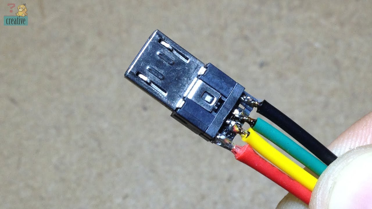
Type A connector is linked to the charger or PC and a microSD connector is plugged into the phone. The USB device that uses full speed bandwidth devices must have a twisted pair D and D- conductors. USB cable has four conductors two for power and two for data.
Please download these usb to rj45 cable wiring diagram by using the download button or right click on selected image then use Save Image menu. The green wire is the positive data wire. The most cost-effective method to make RCA to USB adapter cables is to use a USB.
NRZI Non Return to Zero Invert encoding scheme used to send data with a sync field to synchronise the host and receiver clocks. Usually BLACK wire should be 20-28 AWG. Here is a picture gallery about usb 20 wire diagram complete with the description of the image please find the image you need.
USB Data - usually WHITE wire should be 28 AWG. RCA audio and video cables can split fray. The USB cable provides four pathways- two power conductors and two twisted signal conductors.
Type CMR riser cable Type CM commercial cable USB20 Universal Serial Bus Specification revision 20 also referred to as the USB. USB C cable wiring diagram. 1 trick that We.
Below is the pinout of a typical standard male 9 pin rs232 connector this connector type is also referred to as a db9 connector. This article mainly introduces the USB C cable wiring diagram the pin definition of the 24Pin USB Type C interface and how to connect the core wires as a reference for hardware design. Type-A USB pinout diagram micro USB pinout diagram along with USB wiring diagram.
Although the standard wire colors in the USB cable are red black white and green dont worry if that is not the case for your cable. USB is a serial bus. Jackets for Telecommunications Wire and Cable.
Assortment of usb to rj45 cable wiring diagram it is possible to download for free. Each of these colors indicates the purpose of the wire whether for charging or data transfer. The standard colors found on the inside of USB cables are red black white and green.
Cables and Connectors Class Document Revision 20. The USB 30 specification is the combination of the physical SuperSpeed bus combined in parallel with the physical USB 20 bus. We hope this article can help in finding the information you need.
Print the cabling diagram off and use highlighters to be able to trace the signal. In general youll need an integrated circuit that can be powered by USB and that is designed for this kind of conversion. The blue wire is the negative data wire.
In USB data cable Data and Data- signals are transmitted on a twisted pair. The data is transferred through the D and D- connectors while Vbus and Gnd connectors provide power to the USB device. Usb 20 wire diagram is among the most.
For a USB-A 20 the connection looks like. On Usb Otg Cable Wiring Diagram. The USB 30 specification adds two sets of Shielded Differential Paired wires labeled as SDP.
The USB cable provides four pathways- two power conductors and two twisted signal conductors. The data wires are 28 AWG the power wires are 20 to 28 AWG. The cable has the original 4 wires of the USB 20 specification DD- Power Ground plus the one added by the USB 30 specification.
Its often challenging to determine the proper link of all the cables so a USB Wiring Diagram can help. Usb 20 Wire Diagram Boulderrail pertaining to Usb 20 Wire Diagram image size 458 X 395 px and to view image details please click the image. USB A B and Cable Pinout.
The complexity and intricacy of wiring a USB cable requires specialist tools. The power cores are un-twisted and the data lines twisted. When you use your finger or even the actual circuit with your eyes its easy to mistrace the circuit.
One trick that I. Rs232 cable pinout rs232 to usb wiring diagram. The USB 31 specification spells out exactly how to make this and any other USB C -to- USB legacy cable.
This cable is not transferring data or files it is only for viewing images on RCA-equipped. It uses 4 shielded wires. I am wondering if there is a way to wire an RCA cable into a USB Cable for Video Signals.
USB 30 Cable Diagram. April 8 2018 by faceitsalon. USB A B 20 and 30 Cable Pinout.
USB Male A to 3 RCA AV AV TV Adapter Cord Cable. May 24 2021. The USB device that uses.
Longer cables will use 20 AWG for power. Usb to Rj45 Cable Wiring Diagram Gallery. Trailer Wiring Diagram is a simple yet helpful way to know the proper way of wiring your trailer efficiently and properly.
With this kind of an illustrative manual you will be able to troubleshoot prevent and full your tasks easily. The orange wire is a positive power wire with 5 volts of DC power.

What Each Colored Wire Inside A Usb Cord Means Usb Electronic Schematics Diy Security Camera

Pin On Diy For Kids
Famous Front Usb Wiring Diagram Contemporary Electrical And At Diagrams Sata To 10 Usb Cable Electronics Basics Electronic Circuit Projects

Telescopes Adapters For Smartphones Photography Android Sony Xperia S Sony Xperia Z Schema Electronique Electronique Informatique

Micro Usb Wiring Diagram Micro Usb Micro Usb Cable Usb

Digital Wall Calendar And Home Information Center Electronic Engineering Electronic Circuit Projects Electronics Basics

Usb Wire Color Code The Four Wires Inside Color Coding Usb Coding

Apc Ups Cable Usb To Rj45 Ethernet Wiring Usb Electronic Circuit Projects

Usb Color Code And Usb Definition Color Coding Electronic Schematics Coding

Usb Cable Diagram Ideas Of Sata To Wiring Inside 9 Diagram Wire Cat6 Cable

How To Wire Usb Connector Usb Wire Diagram Instruction Download Usb Design Usb Usb Type A

Micro Usb Wiring Diagram Micro Auto Wiring Diagram Schematic Usb Electronics Micro Usb
Build Micro Usb Cable Youtube Micro Usb Cable Usb Usb Cable

Usb Wiring And Color Code It Depends On The Manufacturer Usb Electronics Hacks Color Coding

Usb Cable Extension Different Wire Color Youtube Usb Cable Usb Cable

How To Make Your Own Motorola Factory Cable In 2021 Usb Electronic Schematics Android Diy

A Circuitry Diagram Is A Simple Graph Of The Physical Links And Physical Format Of An Electric System Or Circuit It Shows How The El In 2021 Serial Port Usb Usb Cable

Pin En Electronic Shopar Aaesshops Com In 2021 Micro Usb Cable Micro Usb Usb Cable

Micro Usb Wire Diagram Copy Usb Wire Diagram Schematic Micro Wiring Cable Power Color Code Otg Usb Micro Usb