gas interlock wiring diagram
Wiring Diagram Book A1 15 B1 B2 16 18 B3 A2 B1 B3 15 Supply voltage 16 18 L M H 2 Levels B2 L1 F U 1 460 V F U 2 L2 L3 GND H1 H3 H2 H4 F U 3 X1A F U 4 F U 5 X2A R Power On Optional X1 X2115 V. Describe and identify the diagram component U.

15 Wiring Diagram For Lawn Mower Kohler Engine Engine Diagram Wiringg Net Diagram Wire Engineering
Prices Technical Instructions Buy Now.

. Fuse the 230Vac power supply according to the fan currents 2A. Exhaust fan interlock wiring diagram. Mains Input 230VAC Single Phase.
This panel air switch estop and 25mm gas valve 190 del vat. CT1200S Wiring Diagram 1. The design of the Gas Minder ensures that there is no gas flow to burners unless air extraction is present.
As Contactor M1 energies its all normally Close NC links open and the other normally open NO links used in the circuit close. We also design and manufacture a full range of gas pressure proving systems and gas detection systems for school laboratories and boiler houses. This prevents a build up of potentially poisonous gas combustion fumes in the kitchen which would be harmful to the health of kitchen staff and others within the.
It will be controlled through a starter with a 120 volt coil. Part 1 Ignition System Circuit Diagram 1994 1995 Ford F150 F250 F350. Terminal and harness assignments for individual connectors will vary depending on vehicle equipment level.
Turn the key switch to on position. Need help wiring an furnace emergency switch houzz i need to add an emergency cut off switch for the gas furnace at the top of my basement stairs but i don t know how to make the connection i know it can t be that hard but i can t find anything online to help and my electrician is mia as you can see in my diagram the. Connect as detailed in wiring diagram see section 11 Gas valve.
By wiring any of twenty interlock switches into the Interlock Annunciator Module the BurnerLogix. 100 S Gas interlock system. WIRING DIAGRAM COMPONENT LOCATIONS.
Describe the meaning of the SD in diagram component T. Working of Electrical Interlocking. EXHAUST INTERLOCK a This unit shall be electrically interlocked so that it will operate only when the associated exhaust systems is functioning.
Here is a picture gallery about gas solenoid valve wiring diagram complete with the description of the image please find the image you need. The Intelligas 100s is the simplest most economical gas interlock system that we offer. Volvo C70 wiring diagram fuel pump part 1 Volvo C70 wiring diagram.
A wiring diagram is a simplified conventional photographic representation of an electric circuit. Do i have to interlock all the bathroom fans with the furnace. Collection of exhaust fan wiring diagram.
Connect 230Vac gas solenoid valve as detailed in wiring diagram. Diagram Gas Furnace Control Board Full Version Hd Quality Diydiagram Beatricemonroy It. Part 1 1993 Fuel Pump Circuit Tests Ford 4 9l 5 0l 8l.
Solenoid safety interlock switch circuit diagrams of components with guard non contact magnetically coded toggle wiring diagram for idem switches 2018 catalogue by how to install sentrol guardswitch fortress interlocks amgard pro series 301 bt door monitoring a tgard architectures pt 1 what er relays and where china high quality key 4. Diagram Ruud 80 Furnace Control Wiring Full Version Hd Quality Amanual Artsconnection It. When we push the ON-1 button to energies the M1 Contactor or starts M1 Motor then circuit complete through Fuse Overload relays trip link OFF Push -1 and ON Push 1.
Diagram a is the more general case in which lights l 1l 2 and the fan are all powered by separate power sourcres. An exhaust air flow proving switch shall be used Refer to sheet exhaust interlock for typical application and wiring diagram for electric hookup. UNDERSTANDING TOYOTA WIRING DIAGRAMS WORKSHEET 1 1.
Gas Safe regulations and BS6173 both require a gas interlock system to be fitted. 1998 1999 Shift interlock WARNING. A pressure switch should always be used in conjunction with the universal in-line electric fuel pump.
To turn the system off turn the key switch to off position. Ford Truck Technical Drawings And Schematics Section H Wiring Diagrams. Merlin CT1200S Gas Interlock System Troubleshooting Guide SS Northern Ltd 4 3 Operation Instructions 31 How to turn the system on and off 1.
An active fuel blinks if any gas interlock is open. The gas interlock system for commercial kitchens Tel. What is a furnace disconnect switch.
Acura SLX 1998 1999 wiring diagrams shift interlock Year of productions. An IP55 rated enclosure is used to house the unit which is designed to operate with a 230 volt gas solenoid and either an appropriate air differential. Verify input power voltage before connecting to starters or contactors.
Describe the meaning of the C13 in the diagram component Q. What is the correct way to wire the fan and furnace in a new home. And motor M1 Starts to run.
Turn the Fans On. ISP-3 Interlock System Pack. Describe the meaning of the 2 in diagram component S.
Exhaust fan interlock wiring diagram. Referring to the wiring diagram Figure 2 on page 8 the operating control and auxiliary limits 1 2. Describe the meaning of the G-W in diagram component R.
Call now to order 02381 290444. Safety Interlock System Installation Instructions. To correct rotation of fans reverse any two leads from the 3 phase starter to the fan.
When trying to locate a component in a wiring diagram and you dont know the specific system where it is located use this handy component locator to find the system wiring diagram in which the component is located. ICC Motor Carrier Safety Regulations stipulate that the fuel pump must not continue to operate after the engine stops. GM-4 control unit DPSA-20 pressure switch DK-1 duct kit EM-1 remote emergency stop button.
Then go to that system and locate the component within the wiring diagram. York Diamond 80 Furnace With A Rodgers 50a50 241 Board That I M Fairly Certain Just Fried Was Trying To Move From. 1989 E150 Power To Coil Ford Automobiles.
Fuel Pump Wiring Diagram 1993 1995 F150 F250 F350. Comprehensive installation instructions for Pressure Safety Switch Z-13061. This ensures that the commercial kitchen ventilation system is working before the gas is turned on.
1995 Ford F250 Cd Radio I Dont Have A Wireing Diagram That. Amana Gas Dryer Wiring Diagram Wiring Diagram For Whirlpool Gas throughout Gas Solenoid Valve Wiring Diagram image size 554 X 268 px and to view image details please click the image. Diagram Suzuki Fr 80 Wiring Full Version Hd.
Interlock Connection Fixed Adjustable Fixed RES Heating Element H Adjustable by Fixed Taps RES Rheostat Potentiometer or Adjustable Taps RES Diode. SS Northern is one of the UKs leading designers manufacturers and suppliers of the latest range of gas safety products including gas ventilation and gas interlock systems for use in commercial kitchens.

Furnace Parts 1 Gif 553 630 Furnace Repair Refrigeration And Air Conditioning Hvac Training

Split Air Conditioner Wiring Diagram Electrical Wiring Diagram Thermostat Wiring Electrical Circuit Diagram

Failsafe Interlock Design Electronic Engineering Design Fails Electronics Circuit

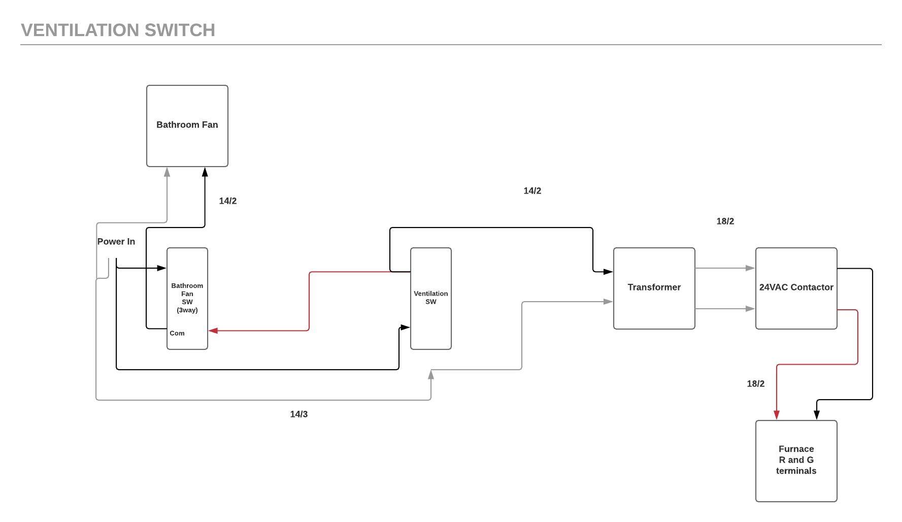
Ventilation Switch Wiring Shd Electric Inc

Craftsman Riding Mower Electrical Diagram Wiring Diagram Craftsman Riding Lawn Mower I Need One For Craftsman Riding Lawn Mower Lawn Mower Riding Lawn Mowers

Power Door Lock Actuator Wiring Diagram Door Locks Electrical Wiring Diagram Door Switch

Failsafe Interlock Design Electronic Engineering Design Fails Electronics Circuit

Gas Furnace Parts And Functions Operation Explained Youtube In 2021 Refrigeration And Air Conditioning Hvac Maintenance Hvac Air Conditioning

Club Car Ignition Switch Wiring Diagram Club Car Golf Cart Ezgo Golf Cart Golf Carts

45 Inspirational Honeywell Switching Relay Wiring Diagram Honeywell Relay Electronic Parts

Small Engine Starter Switch Wiring Diagram And Looking For Craftsman Model Rear Engine Riding Electrical Diagram Craftsman Riding Lawn Mower Engine Repair

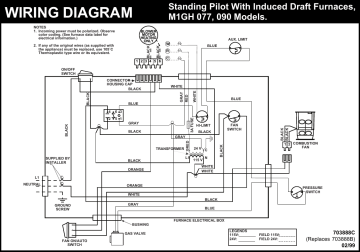
12 Intertherm Furnace Wiring Diagram Electric Wiring Diagram Wiringg Net Gas Furnace Electrical Diagram Electric Furnace

Unbranded M1 Wiring Diagram Manualzz

Payne Furnace Parts Diagram My Carrier High Efficiency Furnace Hvac Page 2 Diy Chatroom High Efficiency Furnace Furnace Diagram

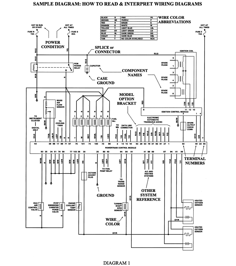
Gm Full Size Trucks 1988 1998 Wiring Diagrams Repair Guide Autozone

18 Electrical Door Interlock Wiring Diagram Wiring Diagram Wiringg Net Diagram Electrical System Wire

A Hot Tub Motor Wiring Outlet Wiring Electrical Circuit Diagram Electrical Panel Wiring

Diy Powder Coating Oven Wiring Diagram Collection Gas Powder Coating Oven Wiring Free Download Wirin In 2021 Whirlpool Dryer Thermostat Wiring Whirlpool Refrigerator
